
Milling Force & Vibration
Let’s talk about milling force and vibration. This movie shows the force (top panel) and tool displacement (bottom) for a down milling operation. The moving dots lets you correlate the dynamic force to the displacement.
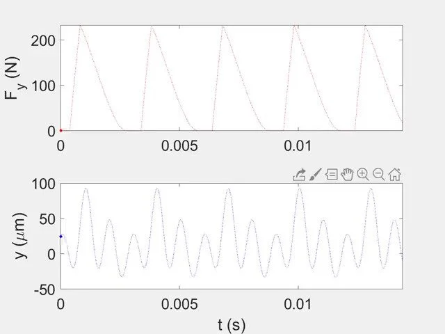
For this simulation, a 20 mm diameter endmill with four teeth and 30 deg helix angle is machining 6061-T6 aluminum. The axial depth is 4 mm, the radial depth is 5 mm (25% radial immersion), the feed per tooth is 0.1 mm, and the spindle speed is 5000 rpm.
We see that only a single tooth is engaged in the cut at any given time and that the force jumps from zero (no cutting) to the maximum value over a short interval for the down milling direction. We also see that the process repeats from one tooth to the next so the cut is stable. However, we observe that, even for stable (no chatter) machining, the tool still vibrates.
The results in the video are for the y direction, where x is the feed direction. If we look through the tool to the workpiece, the y direction is perpendicular to x in this plane. The tool axis is the z direction.
The vibration plot shows the importance of considering the tool dynamics when selecting parameters in the CAM software. It’s not just geometry!